A) It decreases.
B) It increases.
C) It opens.
D) It remains the same.
F) B) and D)
Correct Answer

verified
Correct Answer
verified
Multiple Choice
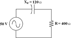
 -What is the true power in Figure 10 -1?
A) 5.73 W
B) 916 mW
C) 275 mW
D) 5.73 mW
F) None of the above
Correct Answer

verified
Correct Answer
verified
Multiple Choice
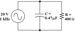
 -What change would increase the power factor in Figure 10 -2?
A) Increasing the value of the source voltage
B) Increasing the value of the capacitor
C) Decreasing the value of the capacitor
D) Increasing the value of the resistor
F) A) and B)
Correct Answer

verified
Correct Answer
verified
True/False
A leaky capacitor can be equated as a capacitor with a resistor being placed in series with it.
B) False
Correct Answer

verified
Correct Answer
verified
Multiple Choice
In a X10 oscilloscope probe input resistance is factor of 10. _ and input capacitance is _ by a
A) increased, decreased
B) decreased, increased
C) decreased, decreased
D) increased, increased
F) B) and C)
Correct Answer

verified
Correct Answer
verified
Multiple Choice
 -If the operating frequency decreases in Figure 10 -1, how does the capacitance value change?
A) It remains the same.
B) It decreases.
C) It increases.
D) It decreases to zero.
F) A) and D)
Correct Answer

verified
Correct Answer
verified
Multiple Choice
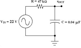
 -If the input voltage increases to 50 V in Figure 10 -3, what is the output voltage at the cutoff frequency?
A) 35.4 V
B) 17.7 V
C) 70.7 V
D) 8.84 V
F) B) and D)
Correct Answer

verified
Correct Answer
verified
Multiple Choice
 -If the operating frequency decreases in Figure 10 -1, how does the current change?
A) It decreases.
B) It increases.
C) It remains the same.
D) It decreases to zero.
F) A) and D)
Correct Answer

verified
Correct Answer
verified
True/False
The total current in an RC circuit always leads the source voltage.
B) False
Correct Answer

verified
Correct Answer
verified
Multiple Choice
 -If the resistor changes to 2.2 kΩ in Figure 10 -3, the new cutoff frequency equals .
A) 1.18 kHz
B) 995 Hz
C) 1.81 kHz
D) 1.01 kHz
F) A) and B)
Correct Answer

verified
Correct Answer
verified
Multiple Choice
 -If the frequency decreases in Figure 10 -1, the phase angle and the impedance _.
A) decreases, decreases
B) increases, increases
C) increases, decreases
D) decreases, increases
F) A) and C)
Correct Answer

verified
Correct Answer
verified
True/False
When the frequency applied to an RC circuit varies, the value of XC varies.
B) False
Correct Answer

verified
Correct Answer
verified
Multiple Choice
 -What change would decrease the power factor in Figure 10 -2?
A) increasing the value of the resistor
B) increasing the value of Vs
C) decreasing the value of the capacitor
D) increasing the value of the capacitor
F) B) and D)
Correct Answer

verified
Correct Answer
verified
Multiple Choice
 -If the resistance is reduced to 4 kΩ in Figure 10 -3, the cutoff frequency equals .
A) 480 Hz
B) 6250 Hz
C) 995 Hz
D) 99 Hz
F) C) and D)
Correct Answer

verified
Correct Answer
verified
Multiple Choice
 -What is the circuit's impedance in Figure 10 -1?
A) 520 Ω
B) 418 Ω
C) 280 Ω
D) 120 Ω
F) A) and D)
Correct Answer

verified
Correct Answer
verified
Multiple Choice
 -If the output were taken across the resistor in Figure 10 -3, the circuit would be known as a .
A) low -pass filter
B) band -notch filter
C) band -pass filter
D) high -pass filter
F) None of the above
Correct Answer

verified
Correct Answer
verified
Multiple Choice
 -If the frequency increases in Figure 10 -1, the phase angle and the impedance _.
A) decreases, increases
B) increases, increases
C) decreases, decreases
D) increases, decreases
F) All of the above
Correct Answer

verified
Correct Answer
verified
True/False
As the frequency applied to an RC circuit increases, the impedance decreases.
B) False
Correct Answer

verified
Correct Answer
verified
Multiple Choice
 -What is the output voltage at the cutoff frequency in Figure 10 -3?
A) 31.1 V
B) 6.45 V
C) 15.6 V
D) 22 V
F) A) and D)
Correct Answer

verified
Correct Answer
verified
Multiple Choice
 -If the frequency is 400 Hz in Figure 10 -1, what is the value of capacitance?
A) 10 µF
B) 6.6 µF
C) 8.8 µF
D) 3.3 µF
F) B) and D)
Correct Answer

verified
Correct Answer
verified
Showing 21 - 40 of 66
Related Exams